
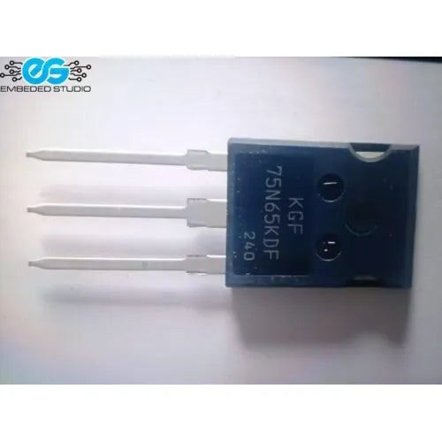
KGF75N65KDF N-channel IGBT — 650V, 100A, 484W, TO-247, with anti-parallel diode
The KGF75N65KDF is a high-voltage, high-current N-channel IGBT (Insulated Gate Bipolar Transistor) with an integrated anti-parallel freewheeling diode, housed in the robust TO-247 through-hole package. Rated at 650V collector-emitter voltage and 100A continuous collector current at 25°C, it is designed for demanding power switching applications including solar inverters, UPS systems, industrial motor drives, and induction heating equipment.
With a low saturation voltage of VCE(sat) = 1.77V (typ.) at 25°C and a maximum junction temperature of 175°C, the KGF75N65KDF delivers efficient, thermally robust power conversion. The integrated anti-parallel diode eliminates the need for an external freewheeling diode in bridge and half-bridge topologies.
Key Specifications:
- Part number: KGF75N65KDF
- Type: N-channel IGBT with anti-parallel diode
- Collector-emitter voltage (|VCE|): 650V
- Gate-emitter voltage (|VGE|): ±20V max
- Continuous collector current (|IC|): 100A @ 25°C
- Maximum power dissipation (PC): 484W
- Collector-emitter saturation voltage (VCE(sat)): 1.77V typ. @ 25°C
- Gate-emitter threshold voltage (VGEth): 6.4V max
- Maximum junction temperature (Tj): 175°C
- Rise time (tr): 115ns typ.
- Output capacitance (Coes): 198pF typ.
- Total gate charge (Qg): 128nC typ.
- Package: TO-247 (through-hole, 3-pin)
Key Features:
- 650V / 100A rating — handles high-power switching in industrial and renewable energy applications
- Integrated anti-parallel diode — eliminates external freewheeling diode in bridge topologies, simplifying PCB design
- Low VCE(sat) = 1.77V — reduced conduction losses for improved efficiency
- 175°C Tj max — thermally robust for high-ambient and high-load environments
- TO-247 package — excellent thermal dissipation via heatsink mounting
Applications:
- Solar inverter switching stages
- UPS (Uninterruptible Power Supply) inverter bridges
- Industrial motor drives and variable frequency drives (VFDs)
- Induction heating systems
- Welding inverters
- Switch-mode power supplies (SMPS)
Note: Mount to an adequate heatsink for operation near rated current. Apply thermal compound between the device and heatsink. Use a gate resistor (typically 10–22Ω) to control switching speed and reduce EMI. Refer to the KGF75N65KDF datasheet for full SOA and gate drive guidelines.


