


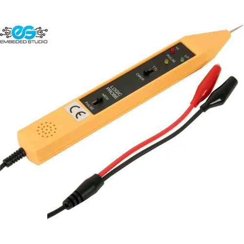
LP2800N logic probe — TTL, DTL and CMOS, pulse memory, 30ns detection
Regular price
Rs.4,500.00
Sale price:
Rs.4,500.00
Regular price:
Sale:
-0%
Shipping calculated at checkout.
In stock, ready to ship
SKU:ES-LP2800N-PROBE

LP2800N logic probe — TTL, DTL and CMOS, pulse memory, 30ns detection
Regular price
Rs.4,500.00
Sale price:
Rs.4,500.00
Regular price:
Sale:
-0%